Network Definition Dialog
The opening dialog requests a problem name,
number of arcs and number of nodes. Options are allowed for
the Pure or Generalized network models. The pure option should
be chosen if all the arc gains are 1. When the Make Random
Problem checkbox is checked, the arc and node parameters are
automatically generated for a sample problem. If not checked,
the parameters are left at zero ready for the student to provide
the data for a specific problem. The purpose of random data
is to allow multiple runs without extensive data entry. Since
the parameters are random, a variety of program situations
can be observed with several runs.
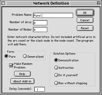
The solution options provide different amounts
of information regarding the algorithm and different levels
of interaction with the student. As the algorithm progresses
it is possible to shift between the options.
- Demonstration: This option
provides a running commentary on the steps taken by the
algorithm as it progresses toward the optimum. The student
is only required to press a button from time to time.
- Instruction: With this option,
the student is required to make decisions about the process
taken by the algorithm. For example, the student must select
the arcs to enter and leave the basis. A hint button provides
various levels of help. Pressing the hint button several
times eventually reveals the correct step. The program prevents
any serious deviations from the proper procedures.
- Do it yourself: Here the student
has the entire responsibility of directing the algorithm.
No hints or corrections are given. If the student is hopelessly
lost, it is possible to shift to the Instruction option.
- Run without stopping: Here the algorithm
is allowed to run to the end without commentary or interaction.
The entry for delay controls the speed of this option. The
program pauses for the specified number of seconds at each
stopping point. An integer number of seconds should be entered
here. Once this option begins, there is no way to change
option until the program finishes.
The Example Network
The example for this section is the figure below.
The Network Modeling pages provide a full discussion of the
network model, however we provide a brief description here.
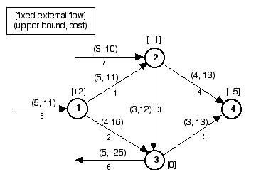
The arcs are the directed lines and the nodes
are the numbered circles. An arc carries flow from one node
to another. For example, arc 1 carries flow from node 1 to
node 2. Arc parameters, shown in parentheses, are the upper
bound for flow and the unit cost of the flow.
Flow is conserved at the nodes. The number in
the bracket at a node is the flow entering or leaving the
network, with a positive number indicating flow that enters
and a negative number indicating flow that leaves. For example
the +2 at node 1 means that 2 units of flow must enter at
the node. We call this the fixed flow. This flow must balance
the flows entering and leaving the node on the arcs. For example,
the flow entering node 1 on arc 8, plus the 2 units of fixed
flow, must equal the sum of the flows leaving the node on
arcs 1 and 2.
Arcs such as arcs 6, 7 and 8, connect to only
one node in the network. These arcs carry variable external
flows. Arcs 7 and 8 provide for flow coming into nodes 2 and
1, respectively. Arc 6 allows flow to leave the network at
node 3. The negative cost on arc 6 represents a revenue.
All lower bounds on flow take the default value
of zero and all arc gains are 1. This program works for generalized
networks, where gains may be other than 1, but that is described
in a later section.
The
First Arc Display
(Click on the title to see a separate window
with the arc display)
The arc display created by the program is shown
in the window. We have entered the arc parameters for the
example, but have not yet clicked on the Iterate button. The
4 arcs appearing at the bottom of the list are "artificial
arcs". They are used to obtain an initial feasible solution.
The yellow area on the upper left provides data for the program
and should not be changed by the student. In general all yellowed
areas hold data or formulas and should not be modified.
The program only solves minimization problems.
The yellow area under the word Min shows the objective function
value. The Phase entry shows the current phase of the two
phase simplex procedure. The Iter. entry shows the current
iteration number and the Status provides a running status
of the solution.
The columns of the Arc Information section hold
the data describing the network model. The column labeled
Cost 1, carries the costs used for Phase 1 of the procedure.
The column labeled Flow gives the arc flows. The program will
put the algorithm results in this column. We discuss the columns
labeled Optimality Information later. They have no meaning
for this first screen display.
The
First Node Display
The node display starts in column O of the worksheet. The
fixed flows of the model are in column Q, labeled Fixed. The
other columns are described later. Notice that there are now
5 nodes, where the original network had only four. The new
node is called the slack node. The artificial arcs all start
at the slack node.